4. Essential Information
Neptus is a C4I (Command, Control, Communications, and Intelligence) framework that is used to command autonomous vehicles.
The core logical interface to talk to the system is the Inter-Module Communications ™ (IMC), that is developed and maintained by LSTS – Underwater Systems and Technology Laboratory. IMC is a message-oriented protocol which defines a set of messages that together define the inter-connection between the systems and Neptus.
4.1. Getting Systems to Communicate
4.1.1. Announce
Before going into detail of how to connect to a vehicle let us introduce the notion of Announce. Announce is a IMC message, containing the information that will allow the surrounding systems to connect to them. This is done by indicating which ports are open to connect to.
As an example look at the following URIs announced from Neptus:
imc+udp://127.0.0.1:6001/

imc+tcp://127.0.0.1:6001/
This indicates that port 6001 is opened for IMC messages for both UDP and TCP protocols.
Another important peace of information, among others, is that in the Announce message it is also included the system location (e.g. LAUV location).
Note
 Since the system location is received through Announce, even if there aren’t any receiving messages through normal channels, it is still possible to know and display systems’ locations.
The Announce message is sent approximately every 10 seconds.
4.1.2. Connections
IMC messages employ the communication protocols UDP (unicast, broadcast and multicast) and TCP over IP.
When Neptus is started, three access ports of IMC communication protocol are opened: two UDP, and one TCP.
One UDP communication access port is opened for the single purpose of listening for Announce messages. This port is fixed and can be one of the [30100, 30101, 30102, 30103, 30104] interval. The listener can connect to any one of these ports. The sender must send the announce message using UDP broadcast and multicast to all of these ports. The address to send these messages is 224.0.75.69. The port interval and address are fixed and should not be changed.
Warning
 These values SHOULD NOT be changed in normal operation. So avoid changes to any
preferences/settings that are named IMC Multicast * or IMC Broadcast *.
These values SHOULD NOT be changed in normal operation. So avoid changes to any
preferences/settings that are named IMC Multicast * or IMC Broadcast *.
The second UDP access port is opened for unicast IMC messages. This will be announced as explained before. Port 6001 is normally the opened one in Neptus and 6002 for the vehicles. This port will be used for normal UDP IMC communication. The majority of the messages circulate through this ports.
Additionally a TCP access server port is also available. This is used for transmitting messages that are by nature more sensitive and their destination is known to be reached.
4.1.2.1. Connecting to a Vehicle Phases
Next, we describe the steps that happen in the two systems connection phase.
Start the communications hub (this is where the router is);
The Neptus and the vehicle are started. The order is not important;
Both systems will start announcing their points of connection;
Neptus will pick up the announce of the vehicle and starts transmitting messages to it (See on Systems List the System List Background Color Codes and System List Symbology Description (Connectivity));
a). This will trigger the vehicle to send messages to Neptus;
Both systems are connected.
Tip
 The Systems List is a good point to check the connection state from Neptus to a system.
4.2. Operators Interfaces
Neptus presents itself in two main interfaces: the operator console, and the review and analysis (see figure Operator Console (left) and Review and Analysis (right)).
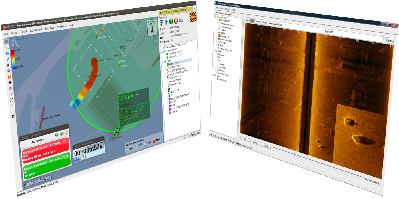
Operator Console (left) and Review and Analysis (right)
The operator console supports the planning, execution, and (simplified) review phases. In the figure we see one possible configuration of the console. As we can see in the figure, the console interface is divided into two main parts: the mission map on the left and the planning elements and controls to the right.
The mission map (left) is where we have the virtual representation of the mission site with the world map, systems location, and data revision overlays. For the world map, the user can choose among a set of available options: tiles from Open Street Map, Google Maps, Virtual Earth, S57 nautical charts or other Internet mapping tile sources. On the latter they are downloaded automatically as needed from the Internet, while on the S57 nautical charts it is required for the user to have compatible charts stored on disk.
On the right side of the console, the vehicle command widgets comprise plan execution controls and, bellow, the mission tree with the elements such as LBL beacon transducer positions and mission plans (both local to the console or stored in the LAUV plan database). Less used widgets are available only by pop-up dialog windows (like the ones seen on the figure bottom left, showing LBL ranges and chronometer) that can be quickly switched on or off by shortcut keys.
The operator console can have various configurations that allow the customization of a specific vehicle or mission situation. So depending on the configuration loaded, the console may have different components/layouts. Additionally each console configuration can hold different profiles that make it possible to change the layout of its components in operation.
The Mission Review and Analysis (MRA) is the interface used to analyse produced data. There are several visualizations available in MRA and they also vary according to data availability (sensor payloads are activated only on operator request). MRA allows inspection of all logged IMC message in both a tabular format or by plotting data present on the messages in time-series plots.
More console widgets and MRA visualizations are available, others can be added to Neptus as plug-ins.
4.3. Core Concepts
4.3.1. World Map vs. Mission Map
World map is not the same as mission map.
World Map:
- Is not stored n the mission file.
- Cache for offline use.
- Use of several map servers (OpenStreetMap, GoogleMap, VirtualEarth, etc.).
Mission Map:
- Store in the mission file
- Add several map elements: marks, geometries, images, etc.
4.3.2. Maneuver and Plan
A maneuver is a basic action of which plans are composed. There several kinds of maneuvers, some more complex than others, as can be seen on Maneuvers section.
A plan (or mission plan) is a sequence (graph) of maneuvers. Payload can be activated and configured.
4.3.3. Mission
A mission is the combination of a location, plans and all mission map elements used. A mission is store in a file with nmisz extension. Each mission should have a single objective and location (for each location or different objectives just use a different mission file, use save as if needed).
4.3.4. Mission Life-cycle
Neptus provides support for different phases of the mission life-cycle so that the same integrated environment may be used to prepare the mission, monitor execution in real-time and revise data that has been collected directly on site or later, in a controlled environment.
4.3.4.1. Planning Phase
A mission usually starts before its actual execution. It usually needs to be prepared beforehand by studying the location characteristics and particularities. With this important piece of information about the survey area, the decision where to deploy vehicles, navigation aids and base station will be a educated one.
If no Internet is available on site, is advised that Neptus is used with previously cached world map tiles of the area, downloaded during the planning phase. For that, it’s simply necessary to browse the area from the Neptus console and the map tiles are automatically cached.
This is the mission phase where plans are created (before or on site). Thus any drafted plan may be tested further by simulation.
On site, the plan to be executed an the transponder’s details must be synchronized with the vehicle.
4.3.4.2. Execution Phase
In the execution phase, the operator is in charge of preparing the vehicles for deployment, monitor the systems telemetry and execute/adapt the mission plans. Also, in a multi-vehicle operation, the several C2s need to be aware of each other and cooperate to achieve the global mission objectives.
4.3.4.3. Data Analysis Phase
The review and analysis phase takes place on site or after the mission (or a plan) is concluded. In this phase, the collected data is processed and analysed to compile the mission results or evaluate individual plan execution in order to adjust and re-plan to achieve another desired outcome.
The first thing to do is to download the data acquired by the vehicle. If necessary, the operator may command the vehicle to come closer to the Manta gateway by ordering a Station Keeping maneuver, which will make the vehicle move only at surface and stay at surface in the target location.
After downloading, the MRA is the tool to be used to process, analyse and display the gathered data.
4.3.5. Log
A log contains all the messages for a specific device and plan. Each time a plan changes or a vehicle becomes idle, a new log is created. Typically a log structure is composed by the following files structure in a day/time of day folders:
- Config.ini;
- Data.lsf.gz (or not compressed as Data.lsf);
- IMC.xml; and
- Output.txt.
Logs already opened may hold additional files and folders containing processed data.
4.3.6. Vehicle Parameters/Configurations
Holds the vehicle internal configurations parameters. Its store in Neptus, and holds default values. These default values may not match the current vehicle values. (see Systems Configuration.)
There are four levels of access: Global, Idle, Plan (configurable in a plan), and Maneuver (configurable in the maneuver in a plan).

Table Of Contents
- 4. Essential Information